Quattro (A Beano Beater??)
By Miles Kingsbury

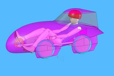
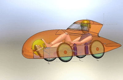
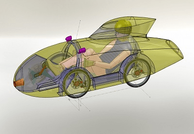
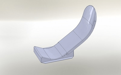
CAD Picture Quattro Initial Design
I have had a very enjoyable season racing my Bubble & Squeak faired trike but the winter is nearly upon us so it’s time to start thinking about a 2010 machine. I could of course use the same trike for the 2010 season but I do love designing and building but more importantly I am desperate to beat Slash.
FUNDAMENTALS
Firstly I would like to recommend two books that have helped me a great deal.
1 The Leading Edge by Goro Tamai which is mainly about solar cars.
2 The World’s Most Fuel Efficient Vehicle by various authors which is about designing and building a fuel cell car.
Before going into details of a new design let’s get the maths out of the way first.
Most of our HPV circuit races are won (by Slash) with an average speed of about 35mph (15.5m/s).
If I want to beat the little s###, I will have to go a little faster or saw up his Beano!
The power required to maintain 35mph is made up of two main elements.
Air Resistance Power = CdxA x½ρV³
Where Cdis the drag coefficient, A is the frontal area in m², ρ is air density (1.2kg/m³ at 20°C) and V is the speed in m/s.
Rolling Resistance Power =CrxVxN
Where Cris the rolling resistance coefficient, V is the speed in m/s and N is the normal force inNewtons(kgx9.81) on the tyre.
There are other mechanical losses such as bearings and chain friction but these are small and I will ignore them in the following examples.
35mph Beano Power
The Cdfor the Beano is probably about 0.12 taking into account gaps, wheels etc. The frontal area is about 0.35m².
Air Resistance Power = CdxA x½ρV³ gives 0.12×0.35×0.5×1.2×15.5³ =94W
The Cris about 0.006 for good cycle tyres, Slash weighs about 65kg and the Beano about 17kg giving a total weight of 82kg.
Rolling Resistance Power =CrxVxN gives 0.006×15.5x82x9.81 =75W
Therefore Slash needs to put out about 169W to maintain 35mph in the Beano. So why is he so sweaty when he gets out after a race?
This is because it is his cruising power and doesn’t take into account accelerating out of corners and climbing hills.
35mph Quattro Power
The frontal area of Quattro is about 0.6m². Let us hope to get the drag coefficient down to the same value of the Beano at 0.12.
Air Resistance Power = CdxA x½ρV³ gives 0.12×0.6×0.5×1.2×15.5³ =160W
Let’s show Mike Burrows some respect and assume the smaller wheels have a slightly higher Crof about 0.0065, I weigh about 73kg and guess the Quattro will weigh about 20kg giving a total weight of 93kg.
Rolling Resistance Power =CrxVxN gives 0.0065×15.5x93x9.81 =92W
This makes a total of 252W which is an attainable figure but does give us an idea of what we are up against.
35mph “Upright” Racing Bike
Putting things in to perspective, a racing cyclist in a crouch position has a frontal area of about 0.3m² and a Cdof 0.9.
Rolling Resistance Power =CrxVxN gives 0.006×15.5x82x9.81 =75W
Air Resistance Power = CdxA x½ρV³ gives 0.9×0.3×0.5×1.2×15.5³ =603W
This makes a whopping 678W! I could probably get a Knighthood if I was able to generate this sort of power output.
New Design
Bubble & Squeak is great fun to drive and is quite competitive, particularly on twisty circuits. I can throw it round corners with gay abandon and if I get it wrong I can just jam on the brakes or take to the grass. However it does have a few faults.
Ground Clearance
With only 25mm of ground clearance and a flat floor, the Trike bottoms out on all but the smoothest circuits, I have also worn away the heels of my expensive Sidi cycling shoes.So when we went to the world championships in Holland this year, I didn’t take the trike as I could have only competed in three of the six events because of rough and uneven surfaces.A ground clearance of 75mm to cope with speed bumps would be lovely.
Turning Circle
Curborough was a nightmare for me this year. After quite a bit of filing and sanding I was still unable to get round the hairpin without severe rubbing of the front tyres. The poor turning circle also makes general manoeuvring tiresome.A turning circle diameter of about 7m would allow me to turn in most roads.
Weight
B&S weighs about 27kg which is less than a Quest but still too much compared with most other recumbents. My sprint results this season have shown that I am carrying too much weight, not to mention the dreaded Hog Hill.
A total weight of less than 20kg should be achievable.
Cooling/Ventilation
The combination of a large bubble screen and poor internal ventilation make B&S very hot, particularly on sunny days. I found that my performance dropped off dramatically after 25-30mins at most races this year. The screen also fogged at some of the events.
Direct ventilation onto my face and screen would help considerably.
Initial Specification
Length 2300mm
Width 730mm
Height 930mm
Weight 18kg TBC
Frontal Area 0.6sqm TBC
Track 650mm
Wheelbase 850mm
Ground Clearance 75mm
Seat Height 100mm
Chainring 80T
Cassette 9 Speed 11-34T Shimano Driving Front Wheel Axle
Cranks 150mm Custom
Wheels 16″ 349 Alloy Rims on Cellite Disks Custom Hubs
Tyres Schwalbe Kojak 349 x 32
Brakes Avid 160mm Mechanical Disks on Front Wheels
Steering Four Wheel – Rear Progressive
Chassis Tubular Steel
Bodywork GRP
SOLUTIONS
My idea of going for four wheels is mainly because I want to try something different rather than going for a Quest type layout. The Quest is a very well sorted all rounder and is hard to beat on practicality and performance.
When I started thinking about the design, I wasn’t planning to compete in pedal car races. Their regulations had a length restriction of 2030mm which was too short for my design; this has now been increased to 3000mm.
The main advantage I can see with a four wheeler is maintaining the cornering stability of B&S with the extra ground clearance I would like to achieve. After all, how many three wheel cars do you see on the roads?
Four wheel steering gives a better turning circle for the same amount of wheel movement and maybe less scrubbing round the corners, but whether it is worth the extra complexity will have to be seen.
I have decided to go for 16″ wheels for a number of reasons. There is now a good selection of tyres for this size, they are smaller and easier to package in particular when steering and they are lighter. I estimate a total weight saving of over 1kg on 5 wheels (including spare).
All four wheels will be the same with a plain hub. The bearings and brakes will stay with the chassis, which should keep the weight down and make it possible to carry a spare.
The wheels are leaning in at 80to give maximum track width with minimum frontal area. I have based this angle on the research that was done for the PACII fuel efficiency car. They suggest that angles up to 80have a very small rolling resistance penalty.
The leaning wheels have made it difficult to get the front drive sorted. I have toyed with various ideas including a lay shaft with short chains and universal joints.
The screen is much smaller than B&S and will have a ventilation duct at its base. It will hopefully hinge like a motorcycle visor to give forward. It is a wrap around screen so it will be easy to fit solar film to keep the heat out.
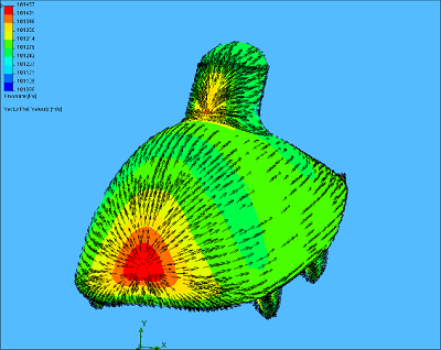
AERODYNAMICS
The basic aerodynamic shape of Quattro is a lot more complicated than B&S or a faired bike. The wheel spats, proximity to the ground and head fairing make it very difficult to imagine what is going on.
Graham Sparey-Taylor has been a great help in getting me started with CFD. He analysed my original model and pointed me in the right direction regarding tweaking the shape.
As can be seen from the initial CFD images, there is a lot going on, particularly around the wheel spats. The result of all this churning is an estimated aerodynamic drag of 18N at 35mph (15.5m/s) which equates to 290w. If the rolling resistance power of about 92W is added, you can see that an old git like me is going to struggle against another old git like Slash in the Beano. More work is needed!………
Quattro Part 2(A Beano Beater??)
By Miles Kingsbury
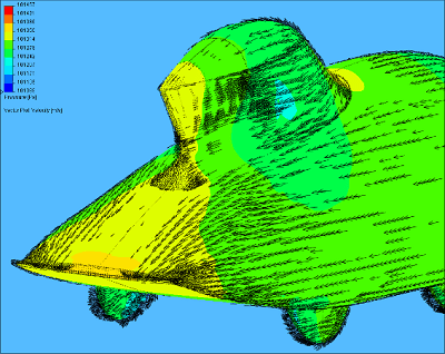
Old shape
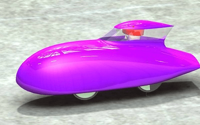
New Shape
As you can see the final shape is very different to the original.
I learnt a lot about airflow in the many steps between the two. I must have done about 30 design changes and test runs using the CFD software to get to the new shape. Each CFD test takes about five hours on a reasonably fast computer.
The combination of the spats and upward sloping shape was causing a lot of drag on the original shape. The slope was encouraging the air to move round from the sides to the underneath but the spats were in the way. This resulted in the air flowing outside the front spats and then inside the rear spats causing a lot of turbulence.
I did the initial CFD tests on shapes without wheels and got some very low drag figures but as soon as the wheels were added the drag went up and a lot of downforce was generated. As any sort of lift causes extra drag, I was determined to reduce it as much as possible.
Wheels
I have always believed that the bottom quarter of the wheel can stick out of the fairing with little drag penalty. This is because it is effectively going a lot slower than the vehicle. The contact point is instantaneously stationary relative to the road. Unfortunately this phenomenon doesn’t show up in the CFD analysis. For this reason, I have got rid of the spats and on the CAD model and have simulated this effect by tapering the wheels from full width at axle height down to a point at ground level.
The flat bottom of the new shape produced parallel air flow underneath the vehicle which did not try and get between the wheels. By having the nose 1/2deg up, this was improved further. The flat bottom also makes the construction and sealing around the wheels easier. I can always add wheel spats or half fairings later if I want.
General Shape
I had one of those eureka moments while in the bath with Goro Tamai (The Leading Edge) reading about down force when close to the ground. Having the nose and tail at the same height makes a lot of sense when you think about it. If an air particle hits the nose, travels along the body and then ends up 200mm higher at the tail then another particle has to fill the gap left. This is bound to cause turbulence with a horizontal tail. This is a problem that doesn’t exist with a trike or bike with a vertical tail.
Wind tunnels and CFD tests are back to front in the way they test a vehicle as normally the air is still and the vehicle is passing through it. Sometimes I find it helps to think about the vehicle parting the air and then letting it go back to where it was before you came along. This way of thinking was demonstrated nicely last autumn while cycling through leaves behind someone on an upright bike. Despite the bulk of the rider being a long way from the ground, the leaves moved outwards about 300mm and then back in a swirling movement as he passed.
Having said this, I was unable to get rid of the vortices in the wake of the vehicle but the drag figures were still coming out very much better than the original shape.
We did all the CFD test runs at 15m/s (Slash beating speed of 35mph) and the drag force was down from 18N to less than 6N which equates to 90W. Adding the rolling resistance power of 92W calculated earlier gives a total of 182W. Slash watch out!!
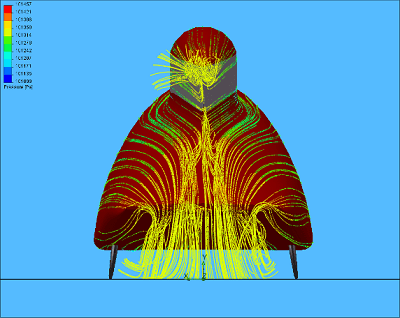
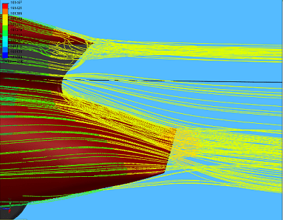

Flow lines over the rear of Quattro showing the trailing vortices.
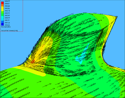
Pressure distribution over Quattro (red high, blue low) showing good positions for ventilation points on nose and base of screen.
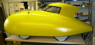
Fairing Mould Making
The fairing production method I am using is in three stages, firstly make a full size model (plug), make a mould from this and then make the part from that mould.
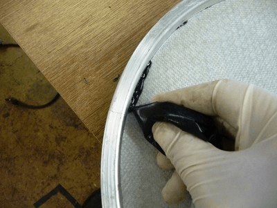
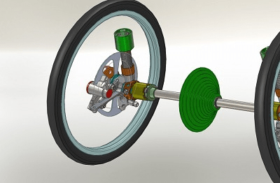
Head Fairing
I thought I would start with the head fairing plug first as in my experience this bit always takes longer than expected because of its tight curvatures. I can also make it separately from the main mould. The top is a revolved aerofoil profile simply constructed from an elliptical nose and curved tail. I did try some more sophisticated shapes but they didn’t give significantly better drag figures and were less practical for my purposes.
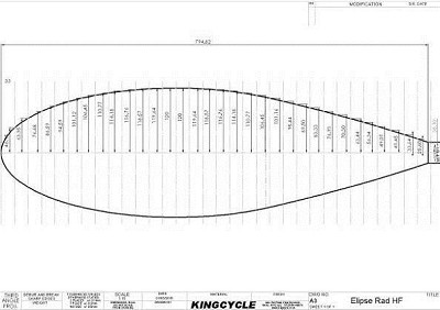
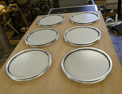
MDF Disk Dimensions
MDF Sawn and Turned Disks
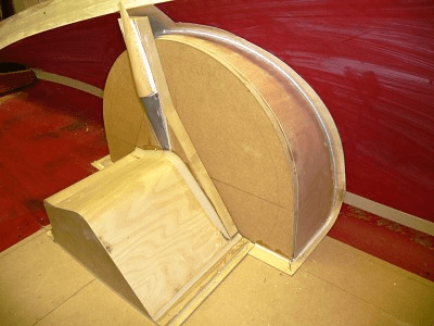
Turning the ‘Kebab’
Because of the problems I have had in the past, I decided to try turning a full revolve in the lathe. I did this by splitting the shape into 25mm thick MDF discs and gluing them together on a 38mm steel tube. The result looked quite similar to one of my favourite local delicacies.
Sanding the head fairing revolve on the lathe was definitely quicker than doing it by hand and it produced a smoother finish. I then added a turned nylon tail and a mock screen and blended it in.

Filling Surface
Smoothed Filler.

Mounted Revolve

Gluing 1.5mm Plywood Screen
Screen Fitted and Sanded
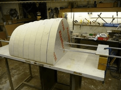
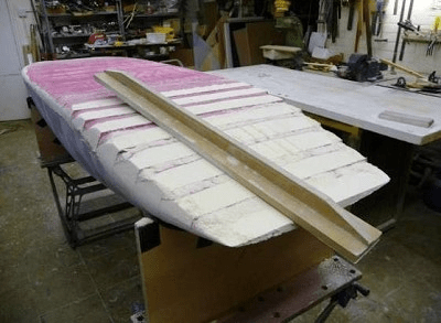
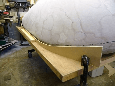
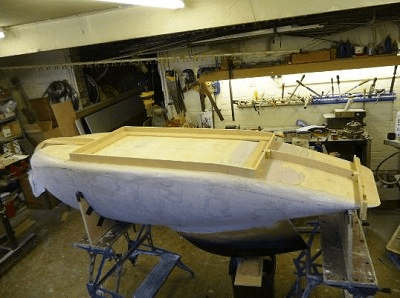
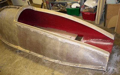
Main Body
The main body plug was made by dividing the CAD shape into 25mm, 50mm and 100mm thick vertical slices and getting these sections plotted full size. I only used the thinner slices for the nose (2×25 and 3x50mm) where the curvature was tighter. The paper plots were then roughly cut out and stuck to Xtratherm insulation boards (I have used Celotex in the past) with double sided tape. I then roughly jig sawed out the shapes and then accurately finished them on the band saw.
I decided to use this type of insulation board as it is a polyurethane based material which meant I could use polyester resin and filler straight onto the surface without it melting.
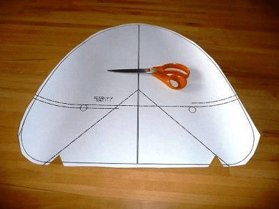
Plotted Paper Section
All Sections
Plots Stuck to Insulation Board
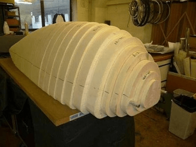
The paper plots also had a vertical centre line and two 19mm holes marked out on them for alignment purposes. The holes were drilled through and a small saw cut was made at the top and bottom on the centre line.
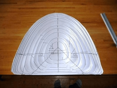
I removed the silver foil backing from the cut pieces and assembled them onto two 19mm diameter steel tubes. I also fitted a straight edge into the lower centre line saw cut. I assembled the sections alternately facing forwards and backwards as I was not sure my CAD shape was perfectly symmetrical. The bench for the assembly is a large fire door which are reasonably light to handle and very flat.
Cut Out Sections
Trial Assembly
Assembled
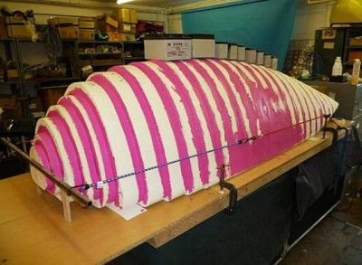
I decided to paint the whole thing with some left over pink vinyl emulsion (other colours will work) which acts well as an adhesive and also makes the intersection lines visible for rubbing down.
Painted Joints
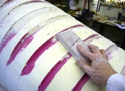
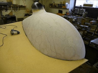
Sanding Top
Sanding Bottom
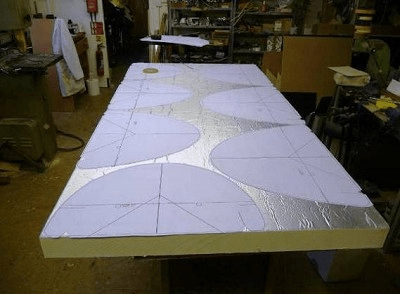
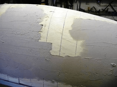
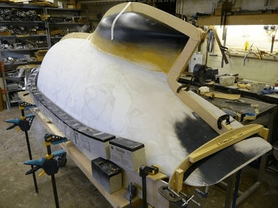
It only took a few hours to get the rough shape finished but this is where I made my first mistake. I decided to use only car body filler to get a hard surface onto the plug.
Part Filled

Top Filled
Plywood Bottom
It is very difficult to get a uniform thickness of filler onto a surface and so I ended up introducing more waviness than I started with. The last plug I worked on was for a school Greenpower electric vehicle, which we covered in two layers of glass fibre. This was really hard to rub down but was quicker in the end to get to a descent finish.
My second mistake was to cover the flat and single curvature sections of the bottom with 1.5mm plywood. I thought this would save time but it didn’t stay flat and caused more work where it distorted.
Head Fairing in Position
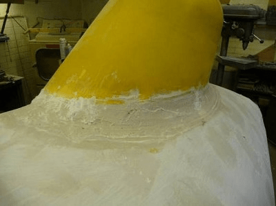
Head Fairing Fillet
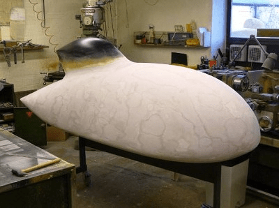
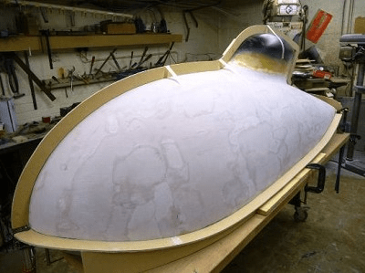
Finished Plug
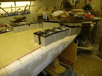
I then sanded an angled face on the top of the plug and fitted the head fairing. It was fixed and filleted using car body filler. The plug was sanded to a smooth finish using 600 grit wet and dry paper but not polished. My moulding man prefers some texture when he waxes the surface.
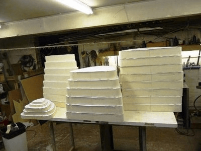
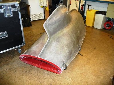
Mould Split Faces
The mould needs to be split for such a shape in order to extract the finished part.
I decided to split the mould into quarters, although a single vertical split would suffice for extraction purposes. The main reason for this top / bottom split is to allow me to add some height in future if necessary. I have been known to make my vehicles a little tight in the past!
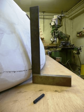
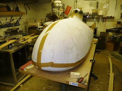
Marking Split Line
6mm MDF Board
Split Support
I found the split line at the widest point by rubbing a crayon along the edge of a large square and then sliding this along the length of the plug. A support strip was then cut to this shape and the split surface glued to it.
Gluing Split Surface onto Support
Split Surface
Parcel Tape as Release Layer
The split surfaces were then stiffened on one side and fixed into position with clamps to the fire door bench. Wood screws were used to on the ends and into the plug where necessary.
I used parcel tape along the centre lines to protect the plug and to act as a release layer while I filled the gaps with the same car body filler.
MDF Splits to Produce Hole in Mould
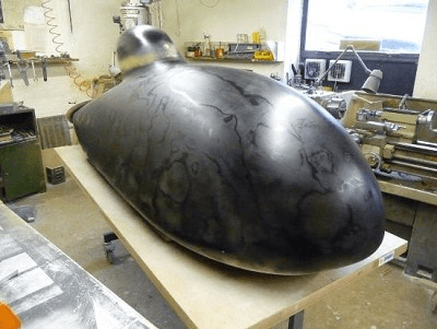
Sprayed Black
Finished Moulds
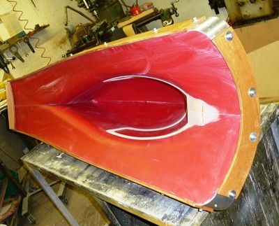
The bottom of Quattro has a large rectangular hole that will probably be filled with a flat sheet of Correx that will be easily removable for wheel changes and general maintenance. This large hole in the mould is also useful as it will allow the mouldings to be easily joined from the inside.
I tried spraying the plug gloss black to hide the patchiness of the filler which I hoped would help show up any waviness in the shape. This did not work and I ended up with a black patchy shape so I decided to leave it at that and work on the inside of the moulds when I got them back.
My brain went AWOL in February so I have been struggling with the internal details of Quattro but it is coming together now.
Things Still To Do
Internal Structural Mouldings Not Started
Suspension and Steering Not Started
Cranks and Chainring Not Started
Screen and Hatch Not Started
Running Gear (Wheels, Hubs & FWD) Being Manufactured
There does seem a lot of work to do still but I am hoping to have Quattro running well before the end of this season. Until then, it is up to someone else to thrash the Slash!!
Quattro Part 3(A Beano Beater??)
By Miles Kingsbury
Final Layout
At the time of writing part 2 of the build, the internal structure of Quattro was going to be similar to B&S with folded and glued Cellite Composite board and the drive was with Z cranks. The difficulty of building in the mudguards and component mountings with the Cellite Board as well as the required torsional stiffness meant that purpose made internal mouldings seemed to make more sense. This also led to the decision to use (slightly) more conventional cranks with a central drive.
CAD Assembly
Monza Trim
Wheels
Gluing Cellite Disk into Rim
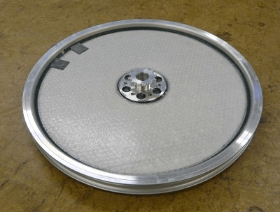
Glued Both Sides
Hub Glued and Wheel Balanced
The 16″ (349) wheels are similar in construction to B&S but are smaller. They only have a simple hub with no bearings or disk brake mount. I have done this so that all four wheels (plus spare) can be the same. The disk brakes and bearing housings will remain attached to the chassis.
Drive
After much deliberation, I decided to use homemade universal joints (UJs) for the front wheel drive which now incorporates freewheels, steering and suspension. My original design didn’t have suspension but after last winter, the Buckinghamshire roads are a little lumpy to say the least! If you speak to an expert, they say that you should always use UJs in carefully arranged pairs otherwise you get an angular output speed variation for a constant speed input. Consulting Wikipedia gave me a complicated formula to work out this speed variation. For a 9 degree wheel camber angle, the angular speed variation came out at about 1.2%, which is the same for a chain running on a 20T sprocket. (2% for 16T, 4% for11T and 6% for 9T Capreo sprocket) Not only that, a suitable, efficient needle roller UJ able to take my torque costs about £40 for a single and £80 for a double and they are heavy steel lumps.
I calculated the UJ torque requirement based on the weight on each wheel of 25kg (250N), 16″ tyre radius 210mm and a road/tyre friction coefficient of 1. Although I could potentially generate more torque, I am assuming that the tyres will slip to limit the maximum torque. The figure I came up with was 52.5Nm, which gave me a guide in selecting the ball bearings for my UJ design and also the size of the Sprag clutch required for the freewheels. By turning a standard UJ design inside out and having the ball bearings in an outer ring, the forces on them is greatly reduced.
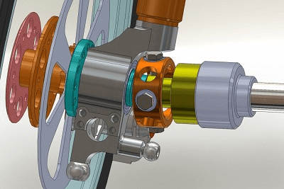
CAD Image Front Drive
Front Axle
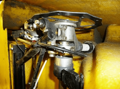
Muddy Oily Reality
Gearing
Because I am very old, I still think in gear inches and I need a very low one to get me up the hills.
B&S had a range of 145″ down to 47″ which were both too high for me. The only time I used top was at Hog Hill and I was badly over geared on the climb. I am naturally a fast peddler and with shorter cranks I am comfortable at about 100-110 rpm. My road bike has 130″ to 32″ and is a little over geared in the Chiltern Hills.
With an extended Capreo block of 9t to 34t, 16″ wheels and triple 45t/60t/72t chainwheels top is 72×16/9=132″ and bottom is 45×16/34=21″
Quattro’s Kojak tyres have an OD of 420mm which gives a 1.32m circumference. At 35mph (15.5m/s), this is 705rpm at the wheel which is 705×9/72=88rpm at the cranks.
All Change
Around Christmas 2010 I discovered an adventure that I felt I couldn’t miss.ROAM was an event organised by Josef Janning from Germany, in which 50 or so like minded nutters in Velomobiles planned to cycle 3000 miles in 26 days from Portland Oregon to Washington DC across the USA in August 2011.
Having sat in the moulds, the fit was tight for me, it would be fine for racing (just) but spending up to 10 hours a day crammed into such a small space would be madness. So I made a tough decision and added a 25mm spacer between the top and bottom moulds. I could always take it out in the future if I wanted a racier version or one more suited to someone of Mr Slade’s stature.
Seat
As the bottom of Quattro is flat and I needed to be able to adjust for leg length, the seat design was a little different to what I had done in the past. By making the back of the seat hinged and adjustable in length, it should suit most riders.
Seat CAD
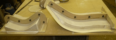
Seat Plugs
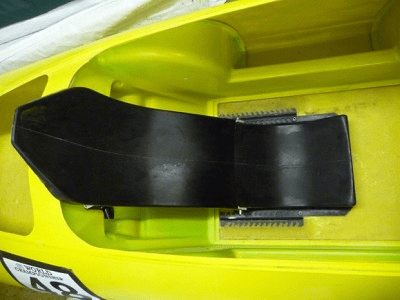
Seat Fitted
Getting in and out
Believe it or not, when the main outer moulds were done, I still didn’t know how I was going to get in and out. Most velos including Quests have reinforced holes like canoes. This would not make the most of my boot space which is one of the big plusses for going with four wheels. I decided to hinge the top at the tail and put the torsional strength back in with two bulkheads incorporated in the inner mouldings.

Cockpit Split With MDF Flange
Main Body Mould
Head Fairing Mould
Inner Moulds
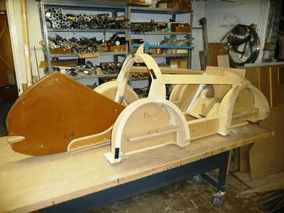
Constructing Inner Mould Plugs
Finished Inner Mould Plugs
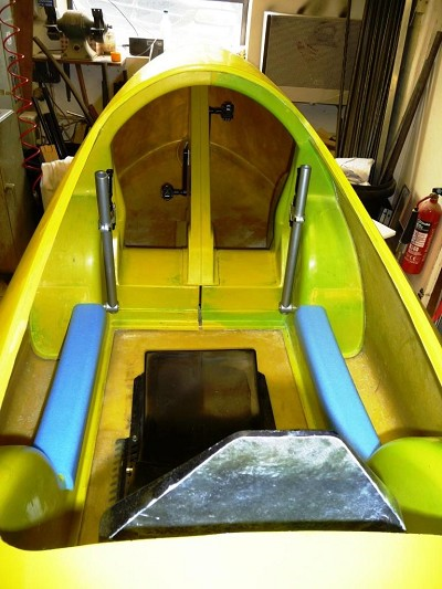
Inside View
The inner mouldings also have a number of other functions and they incorporate mudguards, armrests, dashboard, suspension top and bottom mounts, steering lever pivots, chainset enclosure and seat back mounts.
The inner mould plugs were made from MDF, plywood and filler and had to match the inside of the main moulds, less the finished material thickness. They were very difficult to figure out and make because of having to think inside out on such a complicated shape.
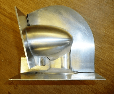
Ventilation
The ventilation is provided by a conical inlet at the nose stagnation point and a hole at the bottom of the screen, the outlets are two 50mm holes in the truncated tail. The centre of the front vent is designed to hold the front headlight.
Ventilation
Tracking Method Showing Underside Cut-outs
Cut-out Cover Moulds
Covers Fitted
Suspension
The finished suspension design is the same on all four wheels and is the combination of a lower wishbone and a McPherson Strut. This arrangement is very common on modern motor cars. I spent many hours thumbing through old Haines manuals and looking on the internet for inspiration. For a while, I was really stuck on the design and decided to call in our resident suspension expert Geoff Bird. We had a very useful chat which put me straight on a number of issues.
The suspension medium I used to start with was a stack of about 20 Neoprene O rings 14mm ID and 5mm section. I thought this arrangement had the advantage of being relatively cheap, simple, light, self damping, with a progressive spring rate and adjustable. The O rings were a sliding fit on the 14mm hard anodised aluminium shafts and sat in cups top and bottom. The top swivel is a combination of an Igus plain bearing for sliding and a standard ball bearing for thrust and turning.
Steering
The steering is similar to B&S with ‘tank’ style levers either side of the rider with short connecting rods to the McPherson struts. The difference being some long connecting rods going to the rear McPherson struts to steer the rear wheels. The idea of steering all four wheels is to give as much turning as possible in the narrowest shape. The rear wheels were initially set up with about 50% of the movement of the front to keep Quattro stable at high speeds.
The kingpin angle in the side view is 75⁰ giving about 55mm of trail and was designed to give zero scrub radius. This means that in the front view, a centreline drawn through the top and bottom pivot points goes through the centre of the contact patch of the tyre with the road.
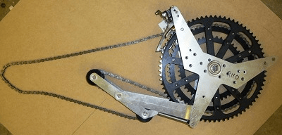
Chainset
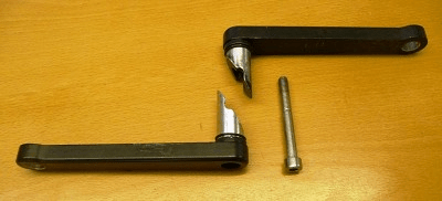
The 140mm cranks are machined from aluminium and are similar in design to what was used on the K-drive a few years ago. They lock together with two 30⁰ wedges and an M8 bolt and they transmit the torque to the chainrings via two 6mm pins.
Monza
In true HPV builder fashion, the first outing for Quattro was at the World Championships in Monza June 2011.
I had one test drive round the car park at work and then off we went. It was a very enjoyable weekend but not a brilliant debut for Quattro.
I took the opportunity of more test drives at the Monza camp site on a wet and very bumpy path. Unbeknown to me at the time, the combination of moisture and bumps caused the o-rings of my suspension to ride over each other. This reduced my ground clearance and caused tracking misalignment front and rear.
Combined with my lack of fitness, Quattro seemed very sluggish and I retired from the 3 hour race after an hour with a terminally jammed chain.
Reading
After the disappointing performance in Monza, I wanted to eliminate some of the variables that could be causing my sluggishness, so I locked out all the suspension with Nylon spacers and disconnected the rear steering. The result was encouraging as I was able to keep up with Mike B and Andrew S with an average speed of 28mph (according to my Garmin) but I still had the feeling that I was pedalling through treacle. The lid was lifting in the blustery conditions, one of the disk brakes was hot when I finished and one of the wheel bearings had already failed, so I was further encouraged that there was still more room for improvement, of course a little engine tuning would also help!
ROAM
Lee Wakefield is writing up our little trip across the USA so I will keep to Quattro based facts and figures here.
Modifications for ROAM
For Monza and Reading, I was using a single chainwheel and a homemade rear mech for my front drive. Although my mech worked OK, I was not convinced it would work reliably for 3000 miles, so I decided to re-design the whole gear system. After experimenting with various standard rear mechs, I decided on a short cage Shimano 105 rear mech, a Shimano triple front mech and a secondary tensioner to take up the slack. Unfortunately, this arrangement did restrict me to a standard 9-26 Capreo block giving me a top gear of 72×16/9=128″ which was nice but a bottom gear of 45×16/26=28″ which I would pay for in the Pennsylvanian hills.
I gave up on the idea of having a reverse gear working for ROAM and decided to go with more conventional heel slots, which I also hoped would give more ventilation.
I replaced all the cheap shielded wheel bearings for some horribly stiff, quality sealed ones as I couldn’t risk more quick failures. The added friction meant that the wheels would only spin for a few revolutions, compared with 15-20 seconds with the shielded bearings.
After much experimenting with my o-ring suspension which seemed like a good idea at the time, I finally gave up and went to more conventional steel springs with squeezed o-rings providing some friction damping. I also discovered the need to track Quattro with the rider’s weight present, otherwise there was a significant error.
Lights
To help make Quattro practical and safe in traffic, I made some mirror housings that included daytime running lights and indicators which Steve and Dave at work wired up for me. The lights and an USB charging socket were run from 5xD cell batteries that I could buy as I needed them on the way.
Mirror Housing Aluminium Plug
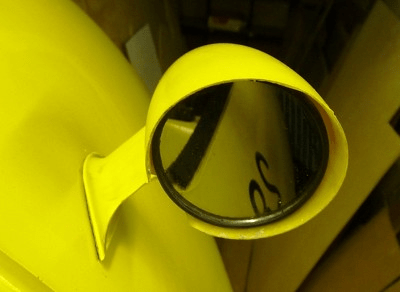
Fitted With B&M Cyclestar Mirror
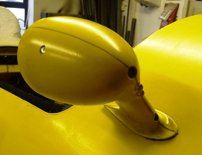
2x Indicator LEDs and 2x LED Daytime Running Lights
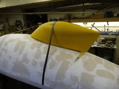
I cut down the head fairing part of the bodywork to make a head out and open cockpit version of Quattro, which was a bit of a bodge but I had run out of time for anything better. I took some yellow foam with me and fashioned a number of covers as I went along, they got gradually bigger and ended up covering about half of the cockpit opening.
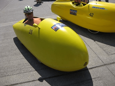
Head-Out Version at ROAM Start
With Partial Foam Cover Added
It is difficult to portray the panic and self doubt I was suffering in the days leading up to our departure to Portland. With 36 hours to go before our departure, Quattro was still in bits and my new additions untested. I still had a plan B in the form of a bagged Kingcycle that could be assembled and taken at short notice.
I finally managed a test drive the day before departure, I climbed from work up to Christmas Common (220m) and back and it all worked! On the climb, it went OK but on the way back I was amazed at the speed, even on a 2-3% slope I was freewheeling at over 30mph!
The only problems were that the individual front brakes pulled badly if not used together and I needed to move the seat position as I skinned the inside of my knees as I was over stretching for the pedals and the bodywork was tight on my shoulders.
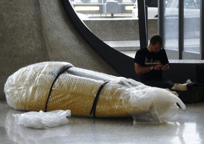
I picked Lee and Martin up from High Wycombe station on the evening before departure and they helped me pack all the spares and tools as well as putting Quattro into its patio heater bag ready for the flight. To keep its weight below the 32kg limit, I had to carry the 6 wheels I was taking in my luggage.
We got to Heathrow in the morning with about 2 1/2 hours to spare and thought we were in luck when we were diverted to priority check in because of the size of our package. With 15mins to go before takeoff, we were still being pushed from pillar to post by the security people and so I told Lee and Martin to go to the gate while I waited with Quattro until the required security person arrived. Another 10mins passed and the lady finally strolled up and asked me to open up the bag. When I explained that I was about to miss my flight, she relented, had a quick peek inside and let me go. I ran as best I could to the gate and was met by a member of staff who re-opened the closed flight and let me on.
My first sight of Quattro when we arrived in Portland, was it being dragged down a corridor and through a doorway with little care and when we got to the hotel that evening, the damage became apparent. There was extensive damage to the front wheel cut-outs, pedal box and both front joints between the top and bottom mouldings.
Thanks to rider and suporter Craig Johnsen I was able to get to a nearby chandlery the next morning and buy a West System Epoxy repair kit and get to work in amongst all the other velos in a conference room set aside as a colourful garage.
Another very short test drive and then we were off!!
The first day was relatively short and easy but I was rather alarmed by the squeaks and creaking noises that had already developed. I convinced myself that Quattro would only last a few days before some kind of terminal failure. The following few days were very tough with climbs up to 1900m over the Rocky Mountains.
It was after one of these climbs that I had my first mechanical failure. Pulling away from a Pizza Hut (typical evening meal) with Lee before we went to the camp site in Missoula MT, my front drive shaft snapped. It was the one thing I was not worried about and I hadn’t brought a spare! Fortunately, the following day was a rest day and we were able to find a machine shop close to the camp ground that could make a new one. The company called Westside Machine & Supply Inc were more used to working on huge tractor engines, so it was not surprising that they only had 3/4in solid steel bar rather than tube but at least it wouldn’t break, even if it did add another kilo. Many thanks to Hans who did the machining from my scrappy sketch.
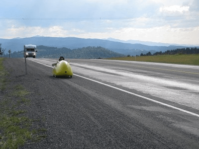
1900m MacDonald Pass
Me (Miles) and Miles (bike shop owner) in Miles City Montana
I was plagued by punctures during the first two weeks and set an unbeaten record of 8 in one day on our way to Kim’s Marina campground, Helena, MT. They were mostly caused by rubbish on the shoulder on which we spent a great deal of our time riding. Most American roads have a shoulder for break downs and cyclists but the quality varies from smooth to ploughed field to scrap heap but in general they are good. The typical culprits were glass, sharp stones and the wires out of exploded lorry tyres. At this stage, I was running Kojaks, as were a number of other riders without my problems. A number of people (including Miles the bike shop owner in Miles City) put forward the same theory, that my front tyres disturb what is lying flat on the road and the rear tyres are then punctured by that disturbed object. This theory was backed up by the fact that I probably had about 20 puncture in all and I think only three were on the front. For quite a few days, I was carrying both my spare wheels as well as an extra tyre and as many mended tubes as I could lay my hands on.
My puncture problems were eliminated completely when I received a set of six Schwalbe Marathon Plus tyres that I had delivered to Ambush Park Campground, Benson, MN at just over half distance.
The only other mechanical issue I had was the failure, on two separate occasions of the 6mm ball bearings in my UJs. I had spare bearings so was able to swap the first one in the evening and the second failure was on the last day.

Velomobile line-up in Chicago
Performance
At the start of the tour, I was one of the slower riders. This was partly because of my fitness and also, my fear of descending in a largely un-tested machine.By the middle, with the addition of a soft cover over about half of my cockpit opening and improved fitness, courage and technique I was able to keep up with some of the fast boys (and girl).
Despite the crude head fairing, I found that I rolled down hills at the same speed or slightly faster than the Quests (depending on rider weight) but I did seem to need more effort on the flat sections. This may suggest good aerodynamic but poorer rolling resistance. The stiff wheel bearings may be part of the cause as well as possible tracking issues.
Effects of slopes
Being new to this velomobiling lark, I was amazed by the effects of even very shallow slopes. In part 1 of my Quattro write-up, I rather optimistically worked out what I needed to do to beat Mr Slade. In a typical circuit race that he normally wins, his average speed is about 35mph or15.5m/s.
The frontal area of Quattro has come out at about 0.42m² and from the CFD tests; the Cd comes out at a value of 0.106. This Cd figure is for a body with no gaps etc, so let’s assume a drag coefficient the same value of the Beano at 0.12.
Air Resistance Power = CdxA x½ρV³ gives 0.12×0.42×0.5×1.2×15.5³ =113W
I used a rolling resistance coefficient Cr of 0.0065 but I was a long way out on the total weight. I weigh about 73kg and Quattro ended up weighing 35kg, not the 20kg I hoped. This gives a total weight of 108kg.
Rolling Resistance Power =CrxVxN gives 0.0065×15.5x108x9.81 =107W
This makes a total of 220W.
The effect of a +/- 1% slope at the same speed is 0.01×15.5x108x9.81 =+/-164W!!
Looking at this another way, inputting a constant power of 200W will achieve an 1% uphill speed of 9.8m/s, 22mph. Downhill 1% gives a speed of 20.8m/s, 46.5mph!
Free-wheeling downhill 5% gives a speed of 38.5m/s, 86.1mph and 10% gives 56.6m/s, 126mph.
These astonishing figures were in some way confirmed by brave Lee in his Quest, while free-wheeling down MacDonald Pass, which is about 8% at the start and his max speed was 72mph despite still using his brakes!!
There is an excellent website created by Tom Compton that I used to get these power, speed and slope figures. www.analyticcycling.com/QCHome_Page.html
Side Winds
My side wind stability was very similar to the short tailed velos like the Mangos. If I was following one down a hill on a blustery day, I knew exactly what gusts were coming my way and I could ready myself for the shove sideways. The Quests were remarkably solid in such conditions and seemed largely unaffected by side winds. Presumably the longer tail brings back the centre of pressure just the right amount. This is something I can experiment with once I have the full head fairing attached again.
Four wheels good
Being the only four wheeled velo, it was interesting to compare the advantages / disadvantages of my setup compared with the others. From a safety point of view, the extra wheel gave me much more stability when crossing rumble strips, which puts the fear of God into the trike riders. Some of them refused to cross a rumble strip at more than 15mph, whereas I could cross them at any speed. There were two trikes that did actually roll over crossing rumble strips during ROAM. None of my 20 punctures gave me any scary moments, in fact on a number of occasions, I didn’t realise that I had punctured until the rim was banging on the ground.
Having four identical wheels and carrying a spare was a great advantage for quick changes and the big boot was great for the evening food shopping trips.
There is a question mark against my rolling resistance and having four wheels probably means more custom parts but all in all I am very happy with my decision to go with a quad. After all, how many Reliant Robbins do you see on the roads these days Rodney?
The engine
By the end of the tour I was struggling again as my lowest gear was not low enough for the relentless hills of Pennsylvania and I was failing to recover overnight for the next day’s action. A nasty bite on my elbow, a septic toe knackered knees and a hernia may have something to do with my physical demise but Quattro kept going more or less consistently too the end.
Getting Home
Despite the best efforts of Mother Nature with a 5.6 magnitude earthquake and Hurricane Irene and with a great deal of help from fellow rider Mike Woelmer in transporting us to the airport, we managed to get home on the right day but on separate flights. This time we wrapped Quattro in bubble wrap and it returned with no extra damage and no problems getting through security. Lee and Martin were on a later flight from the same gate which gave Lee the opportunity of catching Quattro being loaded with surprising care onto my flight.
Escape from Washington before Hurricane Irene
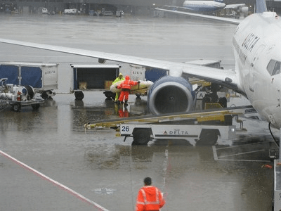
Quattro being carefully loaded onto the plane!
Future
There is talk of a European version of ROAM in 2013 which could be interesting, if it is a little less tough, a little shorter and gives more time for touristy things, I may have a go (Mr Slade has also shown an interest).
For a touring / commuting machine, Quattro needs making lighter and more comfortable with more suspension travel and more shoulder room (for me at least). The 25mm spacer I added to the moulds needs replacing with a wedge starting at zero at the nose and adding 75mm to the tail. This would also help me see over the nose better, helping me to avoid pot holes and debris, which in turn may reduce the number of punctures.
The pedal box has to go and be replaced by a more conventional boom, maybe with a cover. This is because it is impossible to work on as it is. I spent 3000miles listening to it squeaking and creaking as well as poor front shifting. I didn’t have enough time in the evenings to take it apart and see what was going on.
More manoeuvrability is definitely required, I need to perfect the rear wheel steering or get a lot more movement out of the front wheels. I was embarrassed on the ROAM trip on a number of occasions, mainly on the cycle path sections, having to shuffle back and forth to get round a tight corner.
Using zero scrub radius on the steering may not be the best configuration for Quattro, as the brakes do pull quite hard to the side if applied unevenly. It was also the same on B&S. Talking to Frans van der Merwe one of the other ROAM rider / builders, he has about 25mm of negative scrub radius, which means the centreline is outside the contact point. This gives a turning torque under braking that can reduce or eliminate the pulling to one side. Having separate brakes can be a useful feature when racing, as the inside wheel can be very light and lock when cornering and braking at the same time.
When I changed Quattro into a head out version for ROAM, I think I may have made a bad decision. Quite a number of riders were using Flevo roofs or similar to keep the sun off their heads. It may have made more sense for me just to remove all or part of the screen. My intention originally was a motorcycle helmet type visor.
Racing
Back to racing where this all started. At the time of writing, I still have not found out the true potential of Quattro compared with other machines.
I am aiming to make a carbon fibre version this winter and if I add a wedge into the shape, I think the larger truncated tail that this creates will cause a lot of extra drag. I have kept the overall length down to less than 8ft for practical purposes such as transportation. The best CFD test results were with a full length tail, so a stick-on racing tail will probably help my speed.
Having spoken to Mike B, I want to find myself a couple of local roll down test slopes, a high speed one for aerodynamics and a lower speed rolling resistance one. The alternative to this could possibly be achieved on the velodrome at Reading with a calibrated electric motor or SRM cranks. I am also thinking of getting a camcorder and doing some tuft tests, to try and find out what is going on in the real world compared with the CFD world.
© Kingcycle
